| |
The J/105 Owner Guide is now complete. Readers are cautioned that this web version
is copied from a paper version that was prepared in 1992. Any changes in the J/105
since that time are not reflected here. Conflicting or improved or more up-to-date
advice may be found elsewhere on the website. Consider this a 1992 snapshot.
Any discrepancies between the web version and the original paper version are the
responsibility of the website maintainer. This is a rather long web page. If you
would prefer it in smaller chunks or in a different format, please make your
suggestions known to the webmaster.
Table of Contents:
Introduction
Welcome Aboard and welcome to the "J/family" of owners. Your boat is designed and
engineered to be the strongest, best performing, easiest-to-use, and most comfortable sailing boat
of its type.
J/Boats has prepared this guide to familiarize you with rigging, tuning, and operating the J/105.
Before we begin please be sure to:
Complete the enclosed warranty card and mail to TPI Composites, Inc.
This guide is furnished for you benefit, but shall in no way be construed as any sort of warranty
or contract, expressed or implied, creating any obligation on the part of J Boats, Inc., with
respect to any fact or facts or any advise or opinions contained herein.
The sole and exclusive warranty of the product is the TPI Composites, Inc. warranty described
in the appendix hereto and on the Warranty Card furnished with the yacht.
J/Boats, Inc. hereby disclaims any and all warranties, express or implied, including any warranty
of fitness for a particular purpose or any implied warranty of merchantability.
Commissioning Checklist
Pre-Launch
 Read Equipment Owner Manuals
Pre-rig mast and check installation of:
- Halyards
- Blocks
- Electronics
- Shrouds
- Spreader Chafe Guards
- Lifeline Pins
Pre-rig boom
Bottom painted or touched up
Check propeller/strut/zinc
Instrument transducer installation
|
Dewinterize engine and check status of:
- engine oil/filter
- coolant level
- transmission fluid level
- water intakes/filter
- fuel lines/filter
Check all engine control cable attachments
Hook up coupling bolts
Check battery charge
Align prop vertically & mark shaft
Check all hose clamps, tighten as required
Close all seacocks
|
Loose Gear
Fenders
Dock lines
Winch handles
Ignition keys
|
Bilge pump handle
Mast wedges ready
Double-check sling locations
|
Launch
Check for leaks
Check seacocks
Check stuffing box
Engine Start
Read engine owners manual
Align engine and shaft
Start engine
Check exhaust for cooling water flow
|
Check oil press, water temp, charging gauges
Check transmission- forward/reverse
Check stuffing box
|
Step Mast
Hoist spar and lower into boat
Attach headstay to stemhead fitting
Attach backstay & hydraulic cylinder to backstay plate
|
Attach all shrouds and hand tighten
Install wedges and mast boot
Connect mast junction box wires
|
Rigging
Install boom
Lead all halyards to stoppers on cabin top
Rig reef lines
|
Install and connect boom vang
Rough tune spar per tuning guide
|
Systems Check
Fill fuel tanks
Check operation of electrical systems and pumps
Check electronics (optional)
Trial Sail
Raise and lower sails to check for fit
Monitor engine performance and check stuffing box
Check bilge for leaks
Check electronics (optional)
Check reef points and reef lines
Tighten shrouds to straighten mast on both tacks
Getting Started With Your J/105
Generally, your dealer will help you prepare your boat before launching. And in most instances
with a boat this size they will undertake the entire commissioning job. They are experts in the
field and are capable of completing most commissioning tasks.
Before Getting Started
Before you begin assembling your boat, you should become familiar with the different sail control
systems and associated hardware. All running rigging and loose deck hardware items are
shipped from the factory in parts boxes complete with part inventory sheets. To help you properly
install these items please refer to the following rigging sections and the hardware diagrams
in the appendix.
The Commissioning Checklist at the end of the manual will help you to double check that
your J/105 is assembled properly and all systems and rigging function properly. If a boatyard
other than an authorized J/Boat dealer is performing the work, review this list with them to establish
what has to be done and by whom.
- Topsides: Wash off all the dirt and grime accumulated from delivery. Use only non-abrasive
cleaners on the gelcoat. Then apply a coat of high quality carnauba boat wax or a synthetic
poly-based coating. Either finish will prolong the life and sheen of the gelcoat.
- The Bottom: preparation is critical to long-lasting enjoyment. To ensure a professional finish
carefully review the paint manufacturers recommendations for preparing the bottom, and have
your dealer roll or spray it on.
Deck Equipment
The following items are safety and comfort features. They are made of the highest quality materials
and are engineered for your peace of mind and sailing enjoyment.
Steering System
The steering system is carefully engineered to provide "finger-tip" control. This is achieved by
utilizing high quality Harken rudder bearings. The rudder itself is made of unidirectional glass,
with two molded halves bonded together, and a highly reinforced fiberglass shaft. It's engineered
to withstand tremendous shear loads for storm conditions.
- The Tiller is varnished & laminated wood bolted to a custom stainless steel tiller head
mounted to the FRP shaft. The Spinlock adjustable hiking stick is attached on the forward
end of the tiller to enable the helmsman improved visibility sitting further outboard.
Optional Wheel
- Pedestal: is custom molded fiberglass. Inside the "compass cowl" is a standard Edson
chain sprocket which is connected to 7x19 wire to the custom aluminum quadrant. Adjustment
to this linkage is achieved by a set of turnbuckles connected to the steering wire.
These can be accessed through the lazarette locker to starboard of the rudder post.
- Wheel:is a white edson Diamond Series aluminum wheel with a leather cover. It is easily
mounted on the pedestal by aligning the "keyhole" slots together and sliding the wheel onto
the steering shaft. The chrome "Edson nut" screws down over the exposed thread to secure
the wheel in place.
- Emergency Tiller: is installed by removing the access plate, and placing the base of the
tiller over the head of the rudder stock. Fit the emergency tiller NOW to see how the system
works BEFORE you get caught in a situation where you may not have time!
- Before Launching: check the system of cables, quadrant, and sheaves to ensure they are
working smoothly. If the steering seems loose, tighten the turnbuckles by hand and repin
them. Beware that your do not over tighten the cables. Please note that your steering
should be checked periodically for "tightness" and for presence of properly bent cotter-pins.
J/105 Rigging
The running and standing rigging items supplied with your boat are designed for efficiency. A
wealth of racing and cruising experience has gone into the deck layout to make sailing and
boat handling safe and easy to handle by a couple and for a racing crew.
The most unique feature of your J/105 is the J/Sprit system for the asymmetric gennaker. We
believe this system is a major improvement over conventional systems and so let's start by explaining
how it works!
- Carbon Fibre J/Sprit: The carbon fibre pole is custom made by TPI and is designed to
withstand the loads associated with the asymmetric spinnaker without any additional support.
The J/Sprit consists of a carbon tube which is faired smooth and finished with an offwhite
Awlgrip high gloss paint, and two molded end fittings. The forward end fitting has a
"U" bolt which serves as the tack attachment point for the spinnaker as well as the attachment
for the ATN snuffer block. The aft end fitting houses all hardware necessary for the
adjuster line and shock cord retrieval system.
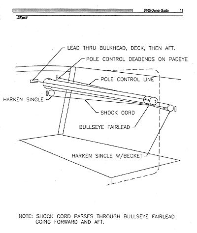
- J/Sprit Launching Line: The line which pulls the J/Sprit out is designed to be operated
without leaving the cockpit. The eye splice is attached to the outboard pad eye on the forward
most bulkhead in the forepeak. The line then leads through the thru-pole blocks on
the aft end fitting of the carbon fibre J/Sprit (be sure the "U" bolt on the other end of the
sprit is up), forward through the bulkhead thru-deck block, up through the deck block, aft (to
starboard) through the bullseye fairleads and finally to the lower Harken cam mounted on
the cabin side to Starboard.
- Asymmetric Shock Cord Retrieval System: The shock cord system allows the J/Sprit to
automatically retract when you uncleat the control line. The heavy duty shock cord system
is set up as follows: attach one end of shock cord to the sprit end fitting pad eye, lead
through the Harken block with becket mounted on padeye on hanging locker bulkhead,
then lead cord through the bullseye on the bottom of the J/Sprit end fitting to the forward
single Harken block mounted on the padeye under the pole opening, back through the bullseye
to the becket, and tension the cord. You may need to experiment once or twice to get
the appropriate tension on the shock cord. It should be relatively easy to fully extend the
J/Sprit, with enough tension on the cord to retract back into the boat. Put a knot in the
J/Sprit cockpit control line behind the cam cleat (in the cockpit) to serve as a stop, so that
the sprit doesn't bang into the bulkhead when released.
- Mast: Rigging the J/105 mast is a straightforward procedure, though it is best handled
by a qualified marine rigger. Should you be commissioning your own spar please refer to the
Hall Spars J/105 Rigging Manual. Be sure all mast related electronics are installed prior to
stepping.
- Hydraulic Backstay: The J/105 is equipped with an integral hydraulic backstay to help
you fine turn your rig and sails for optimum performance. This hydraulic unit is simple to operate,
easy to maintain, and highly reliable. The cylinder is affixed to a toggle on the S.S.
backstay tang on the transom and to the backstay. In order to make the cylinder fit, you
must pull out the S.S. shaft and fully extend it. This is best done by attaching the backstay
cylinder to the boat (w/toggle) and tensioning the main halyard (to pull the mast aft) line up
the backstay and the pin at the toggle on top of the S.S. shaft.
- Boom: Run the reef lines so the red line (port) is led through the port sheaves and the
green line (starboard) is led through the starboard sheaves at both the outboard end and
upper sheave at the gooseneck. The starboard end doubles as the cunningham. Please
look in the appendix for the complete diagram.
- Boom Vang: The Hall Quik Vang is a mechanically operated spring loaded boom vang
with a Harken block and tackle purchase system. This vang system allows for quick and
easy adjustment and acts as a boom topping lift at anchor. The vang is affixed to the vang
plate welded underneath the boom and to the mast at the vang gooseneck located just
above the mast collar. For proper operation and adjustment see the Quik Vang operating
instructions. It is important to be sure the internal spring and stop are properly positioned
so that the boom firmly resists being pushed down too far.
Sail Control Systems
After stepping the mast and connecting the boom, Hall Quik-Vang, Harken Roller-Furler, and integral
backstay, lead all halyards and set-up the remaining sail control systems. These systems
are designed for maximum efficiency and complete ease of handling, making for relaxing
shorthanded sailing in most wind and sea conditions.
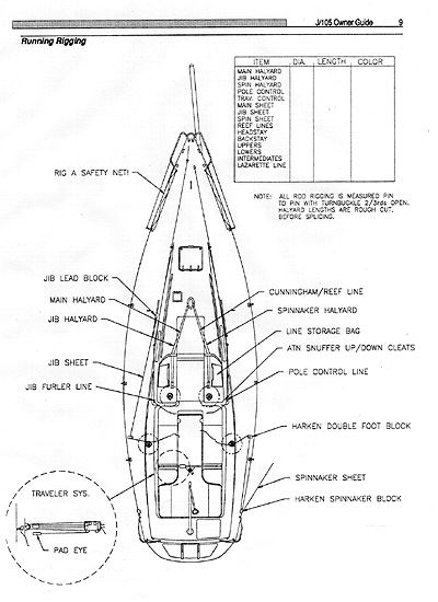
- Main Halyard: exits the mast on the port side, runs through a turning block at the mast collar,
through the inboard port organizer block and then aft through the port double stopper
(inboard hole) and finally to the halyard winch. The tail end is stored in the supplied line
bag which should be mounted outboard and forward of the stopper.
- Jib Halyard: exits the mast to port, leads through the forward mast base block, aft to the
outboard sheave on the organizer block, through the outboard stopper hole, and store tail
in line bag.
- Gennaker Halyard: exits mast to starboard and leads to the inboard sheave and stopper.
- Mainsheet Traveler: is a Harken low friction system. The 3:1 purchase system on each
side controls a Harken Windward Sheeting Car mounted on midrange track. Also included
are two small swivel blocks and a 1" riser for the mainsheet cam cleat. The small blocks
are mounted outboard of the mainsheet traveler ends and allow traveler adjustment from
forward or aft of the traveler. (see diagram)
- Outhaul: is adjusted on the boom and comes pre-assembled from Hall Spars.
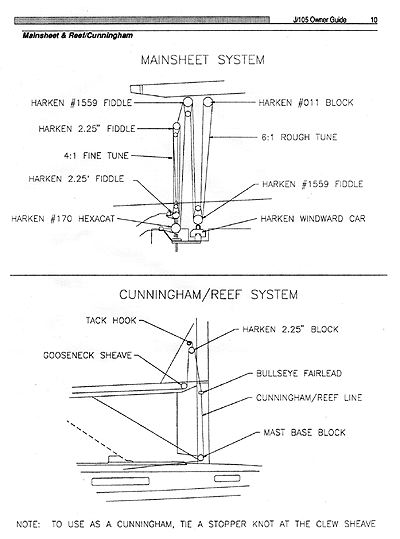
- Cunningham: The cunningham doubles as the starboard reef line. To set up as a cunningham
simply tie a knot at the boom end tail of the reef line. The line leads forward to the
sheave at the gooseneck, up to the cunningham block/hook back down through a bullseye
on the mast, down to the mast base block and aft to the inboard stopper. (see diagram). To
use the continuous reef system simply run the boom end tail through the clew reef grommet,
back down around the boom and tie a bowline.
- Mainsheet: is a 24:1 system (see diagram). The system is designed to allow easy adjustments
of the mainsheet. The location of the traveler also facilitates single-handed sailing
and adjustments. The fixed centerline cleat base rotates to port and starboard for a proper
lead. Be sure to put a "stopper knot" like a figure eight at the end of the mainsheet. (Note:
the standard mainsheet system diagram is effective after hull #50).
- Jib Sheet: is continuous and attaches to the roller furler headsail by a simple knot, leads to
the jib block on the track, aft to the lower sheave of the double turning block on the rail and
finally to the primary winch.
- Gennaker Sheets: lead from the clew aft outside the lifelines through the spreacher blocks
(shipped loose) turning forward to the upper sheave on the double fairlead blocks along the
rail and then to the primary cockpit winches or secondary cabin-top winches.
- Snuffer Control Loop: run through the starboard sheave on the double block fixed to the
end of the J/Sprit aft under the pulpit to the upper Harken cam cleat on the starboard side of
the cabin trunk, back through the middle cam cleat forward to the port sheave on the sprit
end and reattached to the snuffer bridle using the same knot as ATN. (Hull #'s before #50
were not outfitted with these cleats. We are sending a free upgrade kit for all J/105's already
delivered).
Rigging and Systems Diagrams
(Click on thumbnail image for larger image)
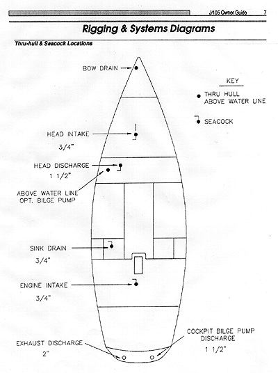
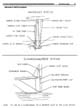
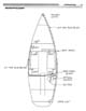
 Thru-hull and Seacock Locations
 Steering Systems
 Running Rigging
 Mainsheet & Reef/Cunningham
 J/Sprit
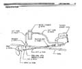 Engine Drive Train
 Fuel System
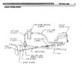 Engine Cooling System
 Manual Fresh Water System
 Head System
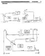
 Electrical Wiring System
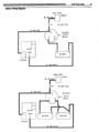 Battery Wiring Diagram
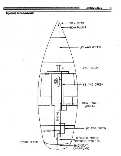
 Lightning Bonding System
Tuning the J/105 Rig
The J/105 comes standard with a double spreader Hall Spars rig. Here is a starting point for rig
tuning as done on Bob Johnstone's J/105 #24 SANDPIPER. As is the case with any new boat,
there will be some experimentation with different tunings. We encourage your feedback.
Tuning
- Headstay length is standard with about 2.5 inches of thread showing under the Harken
Drum with no toggles. The backstay was set up with a toggle under the hydraulic cyclinder
to set the handle forward and the release aft. Mast step bolts are positioned in the middle
of the slots. No mast wedges are installed to start. Rake from the back of the mast to a
weighted main halyard is 30" on the cabin top.
- After taking up the shrouds hand-taught to center the mast using the main halyard to equalize
to the rail outboard of the chainplates, apply maximum backstay on the cylinder to bend the
mast.
- Tighten the upper shrouds equally to port and starboard with a wrench as far as you dare
without stripping the threads.
- The same goes for the intermediates.
- At this point, the front of the mast will be against the forward edge of the mast hole in the
deck. Run a jib sheet around the front of the mast from one turning block to the other and
winch back the mast to permit insertion of the forward mast wedge. Insert the remaining
mast wedges. You may have to slice the back of the mast boot (collar) for this operation.
- Tighten lowers hand tight, being particularly sure that the mast is not inverted because the
asymemetric spinnaker will make it even more so. In fact, be sure to leave your mast bent
in heavy air by NOT releasing the backstay going downwind.
- Double check your handiwork by looking up the back side and front side of the mast to be
sure than it is straight from side to side.
- Go sailing in 12-14 knot winds with max backstay. Take up on the leeward upper and intermediate
by two full turns each with a wrench. Release backstay to intermediate position and
take up on the leeward lower (hand taught). Tack and repeat the process on the new
leeward side.
- Check the straightness and repeat the process making minor adjustments to leeward rigging
only to correct.
The Asymmetrical Spinnaker
Rigging the Snuffer System
- It is important to use a lifeline net forward to help retain the snuffer when underway. Tie
lace lines between lower lifeline (p&s) from the bow pulpit, aft to the second vertical stanchion
bases, if you want to avoid drilling holes or eyestraps.
- Tape the protecting shackles on the jib roller furling drum to avoid snaring jib sheets and
snuffer or spinnaker.
- Shackle the double block to the end of the bowsprit U bolt for snuffer control lines.
- Snapshackle (with swivel) the spinnaker tack to bowsprit U bolt, with snuffer lying in/over
the center gap of the pulpit.
- Detach the snuffer "down" line from the collar bridle, feed it aft through the double block
on the pole, then back forward through the second sheave and re-attach to snuffer collar bridle
with the same knot -- which shouldn't slide.
- Pull loose snuffer control lines aft under the bow pulpit and drop over primary winch base.
(please refer to J/105 Newsletter for further refinements.)
Sailing with the ATN Snuffer
- Lift snuffer skirt to expose clew to attach spinnaker sheets to spinnaker. Pull down snuffer
over sheets.
- Attach spinnaker halyard and hoist to masthead to see that colored stripe on side of snuffer
is straight and that snuffer control lines aren't twisted. NOTE: The spinnaker jibes behind
the snuffer control lines which is one reason the control lines are mounted at the end of the
pole and why it's desirable to keep them reasonably taught (tied to a stanchion or grab rail,
or over winch when sailing). An advantage of this system versus cruising gennakers is that
it's easier to pull down the snuffer when the force of the pull is close to and parallel to the
luff of the spinnaker. On a cruiding boat, this sometimes means a perilous trip to the bow in
rough seas. Not with the J/105.
- Drop the halyard and lay the tube along the deck with the head of the sail in the cockpit and
down the hatch behind the dodger. Your spinnaker is ready to go when you are....
- To hoist from the cockpit, grab cloth of snuffer, pull it over spinnaker until clew is exposed,
launch pole, hoist spinnaker halyard, un-snuff, roll-up jib, trim spinnaker, all without leaving
cockpit.
- To stow after sailing, detach tack and halyard only, stuffing tube down deck hatch with sheets
and snuffer lines attached. Close hatch on lines. This will save 15 minutes hook-up time.
If cruising demands use of V-berth, stow the entire system in a valise type sailbag on deck
overnight.
Engine System
The engine and fuel systems are engineered to be conveniently accessible for repairs and
general maintenance. Located behind the companionway ladder. There is access on the aft sides
(through the cockpit lockers) and in front of the engine from which all important functions can
be reached; including water strainer, fuel injectors, fuel filter, fuel primer, expansion chamber,
and alternator.
Before starting the engine read the engine manufacturer's owner's manual for proper break-in
and operating procedures. Once the engine is running, inspect it for any discrepancies, like oil
leaking, excessive water leaks, or anything out of the ordinary.
- Engine Control Panelis mounted in the cockpit. It contains the starter, warning lights,
and gauges. The throttle and gearshift are mounted on the cockpit wall. Double-check all
mechanical connections between engine and on-deck equipment.
- Engine Bed: is constructed of highly reinforced fiberglass. This provides a superior mount
over wood and is also rot-proof. The engine sits on heavy duty rubber shock mounts to
help isolate the engine vibration from the boat. Check to see that the engine is sitting correctly
on them and the bolts tightly secured.
Drive Train
This is the complete system which propels your boat. It includes the following components;
coupling, stuffing box, shaft log, shaft, strut, and the propeller.
- Transmission is attached to the aft end of the engine and houses the reduction and
reverse gears. These gears generally need little maintenance, but the oil level should be
checked periodically.
- Stuffing Box is aft of the engine where the propeller shaft passes through the hull. It is a
waterproof housing consisting of a rubber "jacket" attached to the tube and a brass bearing
with hose clamps. When the engine is running, check to see that intermittent drips of water
appear where the shaft enters the stuffing box. If the drips are a continuous stream, i.e.
more than one every ten seconds, you must tighten the compression nut on the forward
end of the stuffing box. This requires two large pipe wrenches to tighten the forward nut
over the aft "core nut." It should not get hot when running.
- Propeller is MARTEC folding prop of high quality bronze alloy. Check to see that the
blades on the prop open almost perpendicular to the shaft. The prop is simple to care for
and can withstand years of hard use. However, there are a few easy precautions which
can prolong life:
- Coat it with an excellent silicone grease film.
- Check to see that the joints in the folding prop have a good coating of waterproof
grease.
- Check that all cotter pins are bent over properly.
- Check that the blades are smooth.
- Prop Shaft is stainless and is supported at the inboard end by the shaft coupling and at
the outboard end by the strut containing a rubber "cutlass bearing." Before launching attach
a "shaft zinc" to minimize corrosion. The zinc should be replaced every time the boat
is hauled. Check the "cutlass bearing" within the strut periodically for wear and tear. If it
is loose, replace it.
- Engine/Shaft alignment is set by the dealer to ensure that the engine, shaft, stuffing box,
and prop are properly adjusted to minimize engine vibration. If there seems to be excessive
vibration, notify your dealer and have them investigate.
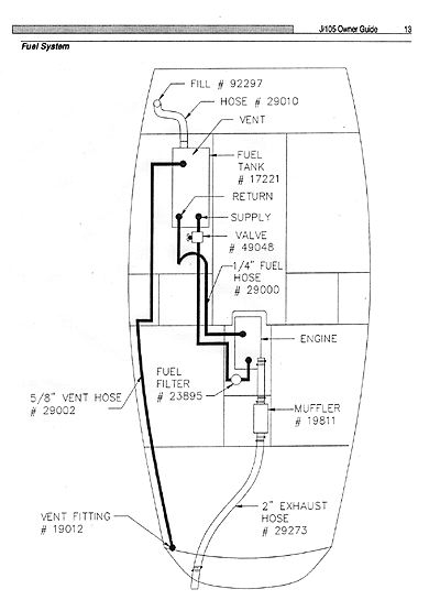
Fuel System
The Fuel System is located centrally in the boat for effective weight distribution. It consists of
the fuel tank, fill hoses and caps; fuel lines and filters and the vent. Use only Diesel fuel in the
system.
- Fuel Tank & Line run from underneath the port main cabin settee, under the cabin sole
and up to the fuel primer pump. From there fuel flows into the injectors. The tank is aluminum
and baffled to prevent fuel slosh.
- Fuel Level Gauge is located on top of the tank. The gauge reflects level (height) of
fuel in the tank, not the quantity. Try to maintain a minimum level of 1/3 to 1/2 tank filled
at all times.
- Fuel Line Shut-Off Valve also sits atop the tank at its aft end. Since many diesel engines
require bleeding after they have been deprived of fuel, it's important that the shut-off valve
be in the "ON" position (lever parallel to piping) anytime the engine is started.
- Fuel Tank Access Plate is atop the fuel tank and provides access inside to clean the tank
or check the fuel gauge.
Engine Cooling System
The engine utilizes a closed system in which a mixture of water and anti-freeze is circulated
within the engine for cooling. This liquid is cooled by a heat exchanger which uses sea water,
in a similar fashion to the radiator on a car which uses air to cool the contained liquid.
- Filler Cap for fresh water (closed) cooling system is located on top of the engine manifold,
and looks like a radiator cap. Check the level in the manifold frequently (ensure engine
is cool). If additional liquid is necessary, add only a mixture of anti-freeze/fresh water.
In colder climates where freezing may occur over the winter, be sure to test the coolant antifreeze/water
mixture for freezing point and add anti-freeze as needed if the system is not
drained for winter layup. Follow engine manual recommendations for proper water/antifreeze ratios.
- Water Strainer is located in the engine compartment and has a two-stage design to prevent
"clogging" of the cooling system. Its simple design facilitates periodical cleaning. To
clean: Ensure the engine water intake thru-hull is closed. Check that the lever is perpendicular
to the intake. Unscrew the wing-nuts atop the filter and remove the strainer from inside
the glass case. Wash thoroughly with water or replace with a new one if badly soiled.
Replace strainer into case and tightly affix lid with the wing-nuts.
Exhaust System
The J/105 is equipped with a water-injected exhaust system which cools the exhaust. It is designed
to both dissipate heat and act as the exhaust muffler. If the flow of cooling water is interrupted
and the engine overheats severely, the rubber hose coming from the engine exhaust elbow
may melt. Always check this hose after an occurrence of overheating. Water can accumulate
in the bottom of the water lift "pot." In fall de-commissioning, the pot should be drained using
the drain plug, or anti-freeze added to the pot so residual water doesn't freeze. If the engine
does not start after a prolonged period of cranking over (starting), be sure to drain the pot
or exhaust loop. Water accumulates here and may fill enough to flow back into engine manifold
if engine does not start.
General Hints to Avoid Problems
- Monitor brightness of cabin lighting and charge batteries as required by running engine.
Batteries are charged by running the engine.
NEVER START THE ENGINE WITH SHORE POWER CONNECTED
- Stop engine with throttle fuel cut-off, then turn ignition key "off."
- NEVER turn battery switch to OFF position while engine is running.
- CRUISING R.P.M. 2400 at slightly less than hull speed. Vary RPM levels periodically
when cruising under power for a long distance.
- Do not run engine at full throttle for sustained period, as breakdown may occur. Most
importantly, find an RPM that runs smoothly. Avoid "vibrating" RPM speeds.
- Mark the shaft coupling where blades are vertical causing least resistance when motor
is stopped and in neutral. Turn shaft by hand to "feather" prop; then lock by putting gear
shift in "REVERSE".
- Keep gear shift lever in "REVERSE" while sailing to prevent "free-wheeling" of the shaft.
Engine Safety Precautions
Due to high temperatures, it is recommended that after running the diesel for more than two
hours you reduce speed to idle and allow excess heat to dissipate for five to ten minutes.
the most common cause of trouble is contaminated or dirty fuel. Your boat is equipped with a
primary fuel filter located in the engine compartment and a secondary filter on the engine. The
wise skipper carries replacement filter cartridges.
Familiarize yourself with the bleeding procedure for the engine and try bleeding it yourself. The
procedure only takes a few minutes after you are acquainted with it, but can be exasperating to
the uninitiated.
Starting The Engine
- If installed, turn VHF and LORAN to "OFF."
- Transmission/Throttle lever:
- Vertical = Neutral
- Port = Forward
- Aft = Reverse
Pull knob on side of throttle/transmission lever out fully, then move throttle forward 1/3 to set
initial RPM's at about 1500.
- Turn ignition key to "ON" position. Audible alarm indicates oil pressure, and will continue
until engine starts. There is an oil pressure alarm test switch on the cockpit engine panel.
- Push the "START" button on panel. Release immediately after start. If it does not start in
ten seconds, release button. Advance throttle slightly after ten seconds, repeat.
- Oil pressure light and audible alarm should go out after starting. If not, stop engine.
- Once engine starts, set throttle at about 1,500 RPM. Check transom for exhaust water.
If no water, shut off engine immediately, check to be sure through hull valve to engine cooling
system is open, or if the sea water strainer is clogged. If indications are normal, warm up ten
minutes.
- Test forward and reverse, and use of lock button for gear, at dock with docking lines in
place. Shifting should be done below 850 RPM's AT ALL TIMES.
- Check for exhaust water from transom periodically. Engine is cooled by sea water via a
heat exchange and enclosed fresh water system. Water should exit from the stern at all times.
Without water exhaust discharge, engine will burn up.
- The best cruising RPM is approximately 2400 RPM. Check sea water strainer for debris.
Ensure thru-hull is open. If necessary, check under hull to see if intake is blocked.
- It is best to keep fuel tank 1/2 full (diesel #2) to avoid debris intake and air locks.
Turning Engine Off
- Place throttle lever in idle position (vertical).
- Let engine cool down.
- Pull fuel shut-off knob until engine stops.
- When audible alarm sounds, turn key off. DO NOT use key to stop engine. Do not stop
engine with decompression lever except in extreme emergency. If decompression lever is
used to stop engine, fuel will spray out and accumulate on top of pistons, creating danger
of explosion the next time the engine is started.
- When under sail you may hear propeller "windmilling" underneath. After shut down put
engine in reverse gear and it will stop. The folding prop will close as speed builds up!
Fueling the 12 Gallon Tank
- When preparing to take on fuel, the following safety precautions should be followed at all
times: Properly secure the boat to the dock using bow, stern, and spring lines.
- Shut of all equipment: Engine, Battery Switch, Radios, Lights, ETC.
- Remove fuel fill plug and clean threads of both plug and deck plate carefully so no dirt falls
into filler opening. Place the fuel hose nozzle into the fill pipe.
- Fill slowly. DO NOT OVERFILL. Marine fuel expands with an increase in temperature.
Thus, fill only to 95% of capacity. If you cannot see the fuel pump, ask the attendant or a
crew member to call out the total gallons.
- If fuel tank is overfilled, fuel will leak out the tank vent located on the transom. This
spillage should be cleaned up immediately.
- After fueling, replace fill plate and wash up any spillage. Go below deck and check for
fumes or leakage. Check bilge. IF EITHER FUMES OR LIQUID FUEL ARE PRESENT,
CORRECT THE SITUATION BEFORE PROCEEDING. Open all hatches and ports to facilitate
ventilation.
- Only after you are totally satisfied that no potentially dangerous condition exists, leave
the fuel dock. Be considerate of fellow yachtsmen.
- In the event of a serious spillage, STOP FUELING IMMEDIATELY. Replace fill plate, notify
attendant so he may warn others and wash down thoroughly all traces of fuel or source of
fumes.
Engine Maintenance
Check the engine, batteries, and engine mounts once a month. Ensure the engine is fastened
securely to the engine mount frames and look for any problems, such as fuel or oil spillage. If
you need help, consult a professional marine mechanic or the engine manufacturer's licensed
mechanics.
Run the engine frequently and at occasional high speeds, even if it is not in gear. One reason
why sailboat engines may burn out within a few years is that they are run infrequently and
lubricating oil is not thoroughly and evenly distributed on all moving parts. Be sure to check
oil and coolant levels often. If you have any doubts about the purity of the fuel you are buying,
use a strainer to filter out water and dirt.
If there is excessive vibration, in other than specific RPM points, loosen the coupling and insert
a feeler gauge all the way around to determine if the engine is properly aligned. If aligned and
vibration persists, check prop for proper balance and uniform opening/closing and be sure that
strut mounting is secure. If there is still a problem, contact your nearest Yanmar Service
Representative.
Construction
Your J/105 is manufactured by TPI Composites Inc. in Warren, Rhode Island. TPI is renowned
throughout the industry as the pioneer and expert in quality fiberglass
yacht construction. Their extensive staff of craftsmen, engineers, production specialists, and
quality control inspectors ensure that your J/105 has been carefully built and thoroughly
inspected.
The technology developed by TPI for constructing sailboats is the most advanced in the marine
industry. Only the highest quality materials are utilized and they undergo constant testing in
TPI laboratories to ensure they meet stringent construction and material specifications.
Materials
- Gelcoat: All J/BOATS have a neo pentyl glycol (NPG) isophthalic gelcoat. NPG iso
gelcoats yield a denser, more frequently branched molecular network which inhibits migration
of water molecules. Because of their structure, these gelcoats offer superior resistance to
moisture penetration, blistering, and fading. They're formulated to "yield" more than other
gelcoats and this "flexibility" improves cracking resistance. Testing also indicates that NPG
ISO GELCOATS produce the highest gloss and the best color retention under harsh exposure.
- Glass fabrics: High performance unidirectional, biaxial, and triaxial fibers are used
throughout the hull and deck. Their use in the sandwich laminate offers superior strength
and stiffness to conventional cloth and woven roving laminates. These unidirectional fibers
are oriented in the laminate structures along lines of stress for greatly improved hull/deck
strength and stiffness. These specially woven fabrics also require less resin for lamination
than low cost fabric matrixes; producing stronger, lighter structures without excess weight.
- Resins: Resins are chemically formulated to TPI's exacting specifications to incorporate
the best balance of properties based on extensive testing. For the hull, a special vinylester
resin is used as a barrier coat behind the gelcoat to prevent moisture penetration. This reduces
the likelihood of blistering within the laminated structure. It is also formulated, like the
gelcoat, to reduce "cracking." The combination of this vinylester resin with NPG ISO gelcoats
and properly specified glass fibers yields the most blister resistant hull in the industry.
A high quality polyester is used to complete inside and deck laminates. Again, a superior
chemical formulation is specified to assure resistance to "cracking" and "fatigue." Furthermore,
its properties also assure high strength and stiffness for the life of the boat.
- Sandwich Construction: is used in all J/BOAT hulls and decks to produce lighter,
stronger, and faster performing boats. A fiberglass sandwich functions similarly to an "I"
beam. "I" beams are used for construction because they make the most efficient structural
use of materials. The inner and outer skins of the sandwich function in much the same
way as the horizontal top and bottom flanges of the "I" beam, and the core works similarly
to the vertical support of the "I" beam. This means consistently lighter hulls and decks can
be produced which are stiff and stronger than conventional solid glass hulls or decks.
Many different cores are available for sandwich construction. TPI uses LLOYD'S OF LONDON
approved CONTOURKORE end-grain basa core manufactured by BALTEK CORPORATION.
It has superior physical properties in performance over any other type, plus
excellent "thermal stability" in warm climates or direct sunlight. Fatigue properties of the
end-grain balsa core are far superior to foam cores, assuring greater longevity and higher
resale value. Balsa also provides excellent impact and puncture resistance.
Structural Components
- Bulkheads: The major structural framing and bulkheads on the J/105 are glassed both to
the hull and deck using non-woven biaxial glass fabric. This provides an increadibly strong
bond between the hull, deck, and frames.
- Hull/Deck Joints: Extremely strong and watertight hull-to-deck joints are created chemically
with aerospace elastomer adhesives, and 3M 5200 high strength urethane adhesive
sealant. The hull and deck flanges have extra glass laminates and are designed to withstand
high local area stresses.
- Hardware: To make your sailing as enjoyable and trouble-free as possible, equipment is
chosen from the best suppliers in the business, such as HARKEN, BARIENT, SCHAEFFER, HALL SPARS
& RIGGING, LEWMAR, ORIGO, AND EDSON. All internal and external
hardware fastenings are engineered or specified for longevity and durability, Backing
plates and additional laminates are incorporated when necessary to ensure reliable fastening
of high load hardware.
- Thru-Hull Fittings: are high quality bronze or glass-reinforced nylon fittings. The metal
fittings are individually grounded to protect against galvanic corrosion. All are sealed with
5200 sealant to ensure watertightness. The hull core terminates several inches from the
thru-hull fittings and is replaced with solid glass to prevent water contact with the core.
- Keel Stub/Sump: This critical hull area is designated using multi-layered solid glass
laminates to accommodate the locally high loads induced by the keel. The keel is seated in
epoxy and thru bolted to the keel stub. A specially formulated epoxy which adheares well to
lead is used to bed the keel. It's highly resistant to water permeation and cracking due to
"thermal cycling". The keel is manufactured to factory specified templates and molds. It is
cast of lead, reinforced with antimony (for strength) and high-strength monel stainless J-Bolts.
Keels made in this manner are far superior to other configurations.
- Electrical System: has a pre-assembled wiring harness and breaker protected central
panel to ensure safety and organization. The wiring follows the industry accepted coloring
codes of the A.B.Y.C.
Plumbing Systems
The plumbing system in your J/105 consists of manual fresh water, manual pumps, and a Raritan
head (toilet). This section will describe their locations and how they operate.
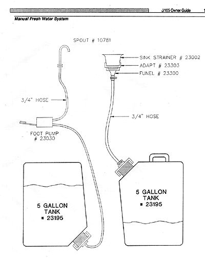
Manual Fresh Water
- Water Tank: is made of polypropylene, is collapsible, and is simple to install.
Simply attach the hose from the foot pump to the tank.
- Optional Water Tank: Part of the Systems Group Package this 20 gallon tank is made of
rotationally molded polyethylene. Connected to it are the following hoses: a) fill hose - located
on the tank top and connecting to the deck water fill pipe; b) feed hose - located
along the tank bottom connecting the water system to the manual pumps; c) vent hose - internal
and leads under the sheerline into the bow compartment.
Thru-Hulls
All thru-hull fittings are made of brass or glass reinforced nylon. For safety reasons, we
recommend that you tape a soft wooden bung adjacent to all thru-hull fittings in the event of
a hose or valve failure. These fittings each have valve-handles. To reduce confusion, remember
long end of the handle indicates the direction of flow.
Pump Systems
Pumps are easy to maintain and just as easily forgotten ... they always happen to seize up when
you need them most. Consequently, take care to keep their screens clean and rubber gaskets/bellows
working correctly.
- Manual Bilge Pump: The manual Henderson bilge pump is installed in the cockpit and is
operated by opening the plastic cover, inserting the pump handle (shipped loose) into the
socket and vigorously pumping with up and down strokes.
- Optional Electric Bilge Pump: Part of the Systems Group Package, the pump is wired
directly with an in-line fuse to the battery switch, so that it is always "on." This useful
feature helps to eliminate most accumulation of water in the bilge.
- Suggestion: Carry a small plastic dinghy handpump to get the bilge completely
dry and to pump cooler water into the sink without having to lift cooler to drain.
Head System
The J/105 is equipped with a certified marine head which is capable of discharging the
effluents into a holding tank or overboard (in compliance with U.S.C.G. regulations). It is easy to
operate and with correct usage and proper maintenance, will provide many years of use. If it is not
taken care of you will most certainly have trouble.
Before operating the HEAD, ensure you have read its manual thoroughly and understand the
proper procedures. Silly mistakes can cause severe "head"-aches at the worst possible time!
And a word to the wise:
PLEASE TRAIN YOUR GUESTS ON HEAD OPERATION. NEVER, NEVER ASSUME THEY KNOW HOW TO USE IT!!
The head is a large pump which takes in seawater and flushes waste into the holding tank or
overboard. Both the salt-water intake and the discharge thru-hulls are in the head area.
Remember open/closed positions on these thru-hulls. It is good seamanship to close the intake
and discharge seacock for the head when not in use.
- Y-Valve: is installed to give you the option to pump effluents overboard when the
vessel is operated outside U.S. territorial waters. Some waters prohibit the existence of a
"y" valve, so the device should be removed (or bolted to the holding tank position) for
navigation in these areas. Conformance with sanitation laws is an owner responsibility.
- Holding Tank: is attached to the head system to satisfy federal regulations. It
is for the retention of sewage and, like the water tank, is collapsible and removable.
When seawater and effluent are pumped through the head, they're pumped into the holding tank by
the action of pumping the toilet handle. The waste discharge fitting on deck is provided
so a shoreside pump-out station (i.e. vacuum cleaner) can empty the tank. With the standard
holding tank, it is not necessary to "pre-charge" the tank by adding water before using the system.
Care should be taken not to overfill the holding tank as effluent can block the vent hose
and may damage the tank ... or worse, burst the hose. If the toiled is difficult to pump, check to
see if the holding tank is overfilled. "When in doubt, pump it out."
The holding tank must be pumped out before winter storage. Pumping a quart of anti-freeze
through the head will prevent the seals and equipment from cracking. For your information, the
following hoses are connected to the tank:
- Waste Discharge Hose from the head
- Pump-out hose leading to the deck fitting
- Vent Hose to vent the tank overboard.
The Final Word!
Be certain the pump on the toilet is pumped 15-20 strokes after waste is
emptied from the toilet bowl to insure the waste is pumped fully through
the hoses.
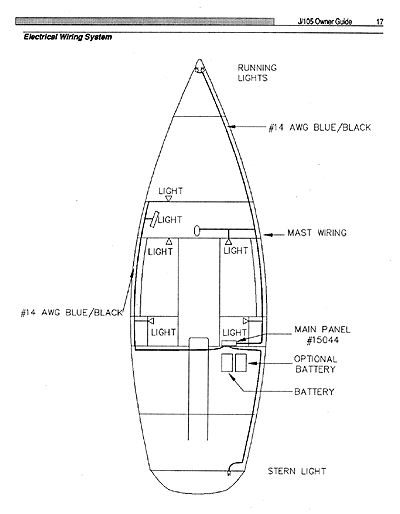
Electrical Systems
The following section describes the electrical system aboard your J/105, how it operates,
where it leads, and how not to get yourself in trouble. Please read this section over more
than once. For wiring code information please refer to the color code diagram.
DC Electrical System
A 12 Volt D.C. electrical system is used throughout for lighting and operation of pumps
and various accessories. the J/105 is standard with one 12 volt 90 amp deep cycle battery.
- Electrical Panel: is the "nerve center" of the system as it controls distribution
and contains all circuit breakers and switches. The J/105 is equipped with a Bass electrical
panel with eight breaker switches. The wiring harness runs from the back of this panel to all
electrical components in the boat. The battery delivers power to the panel with its power
replenished by the engine alternator each time the engine is run. For a 12 volt current to be
delivered to a component, the following criteria must be met:
- Charge in the battery
- Battery switch switched to "Both" position
- Circuit breaker for the component switched "on" (cabin lights, running lights, etc.)
- Local switch on the component itself switched "on"
- Mast Wiring Terminal Box: is located on the upper portion of the bulkhead just inside
the head to port. The mast wiring harness exits the mast just beneath the deck, and is wired
directly to the D.C. system.
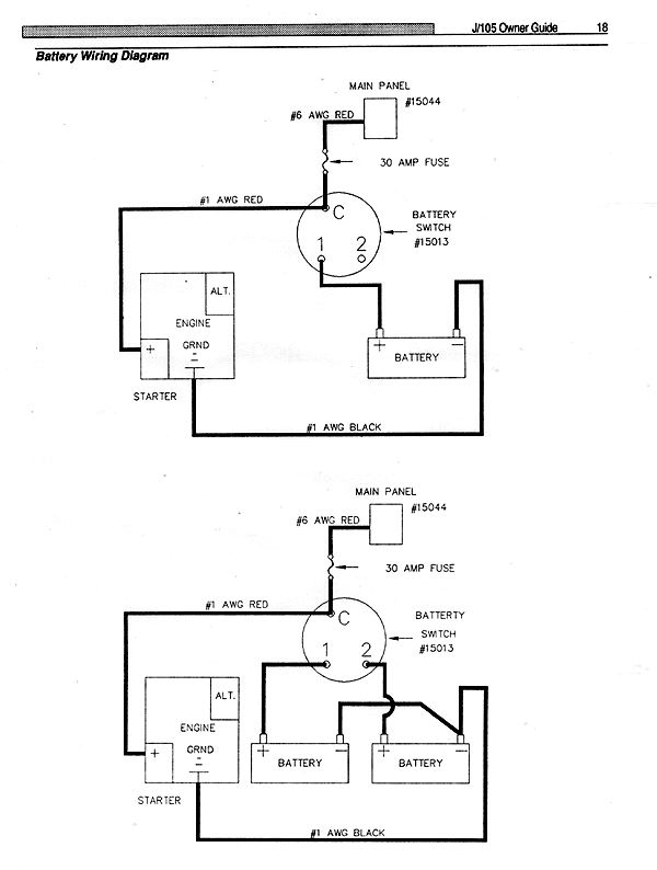
- Battery Switch: The battery switch turns access to the battery ON or OFF to the main
panel and the engine. The standard J/105 comes configured with one battery so select
"BOTH" on the switch. The optional second battery enables full use of the switch and allows
one battery to be reserved exclusively for the engine and the ability to double up the
cranking amps for cold starting in the "BOTH" position. The engine alternator will only
charge the battery selected by the switch, so it is wise to have the switch set to "BOTH"
should you have the additional battery.
- Alternator: is attached to the engine and will create a charging current only when
the engine is running. The output is connected directly to the battery switch to distribute the
current to the batteries.
- Accessories: such as navigation instruments, stereos, radars, lorans can be added to the
electrical panel and the 12 volt DC system. Extreme care and forethought should be taken
in their installation as these are, in general, sensitive instruments and require some
measure of protection. Such work should be performed by a marine electrician. Be sure all
sensitive accessories are not only grounded properly, but that "fast blow" fuses are run off
the panel for extra insurance against damage fo their components.
Safety
Lightening Protection
The J/105 is completely grounded in accordance with industry practice. The mast, shroud
chainplates, stemhead fitting, backstay fitting, engine, and electrical system are grounded to
the keel. In spite of this grounding, there can be no assurance that personnel or the boat will
not suffer injury if the boat is hit by lightning. The following are suggestions only and in no way
guarantee safety in the event of a lightning strike.
- If possible, remain inside a closed boat during a lightning storm. Do not contact any
metallic objects inside or outside the boat.
- Avoid contact with any items connected to the lightning conductive system (mast,
shrouds, etc.) and especially in a manner to act as a bridge between them (mast to
shroud, etc.)
- Avoid swimming during a lightning storm.
If the boat is mildly struck by lightning, check all compasses and electrical gear to determine
that no damage or change in calibration has taken place.
Galley Stove
A non-pressurized alcohol stove is part of the Systems Group Option and is in "ready-to-use"
condition. It is significantly safer than older pressurized models and is a remarkably fast heating
stove, nearly equalling the heating of home ranges. It can boil a 2 quart pot of water in 8 to
10 minutes. Engineered with high quality stainless steel, it will last for years with proper care.
Be sure to read the stove manufacturer's instructions on use and the filling of its cannisters.
You will find it easy to use as long as you follow proper precautions.
To begin stove operation, you must first fill the cannisters with alcohol fuel. Inside the cannister
is a "wick-like" material which absorbs alcohol which once filled will last four hours or more. If
the stove isn't being used for a long period, be sure to place rubber seals over the burner openings
of cannister(s) to prevent evaporation of alcohol.
Safety Equipment
You can never be prepared enough for emergencies which may arise at sea. Current ORC
guidelines may help you in preparation, as will up to date USCG safety requirements. The
ORC Offshore Regulations booklet is available by calling US Sailing at (401) 849-5200.
IT IS THE OWNERS RESPONSIBILITY TO COMPLY WITH ALL FEDERAL AND STATE
REGULATIONS WITH RESPECT TO SAFETY EQUIPMENT; OPERATION OF THEIR VESSEL;
AND SAFETY OF ALL PASSENGERS.
Taking Care of Your J/105
Even though modern construction has helped reduce upkeep, regular attention should be given
to the maintenance of your boat. This includes the fiberglass exterior surfaces, interior
surfaces, and the mechanical and electrical systems.
A well maintained boat will not only bring you years of enjoyment, but most importantly,
will bring you greater personal pride and joy.
Fiberglass/Gelcoat
Apply a marine wax at least twice annually to preserve the "factory fresh" appearance for many
years. Be sure fiberglass surfaces are clean and free of salt before waxing. Abrasive cleansers
should never be used for general cleaning as they can severely mar the shiny gelcoat finish.
On areas difficult to wax, like nonskid, a coating such as "Armor All" will restore its original
luster.
Bottom Paint
Keeping your bottom clean is of paramount importance as it not only keeps off bottom growth,
but maintains passage-making speed. Even though you have applied anti-fouling paint, take a
swim once a month or so (or hire a diver) and scrub the bottom and propeller with a scrub
brush or abrasive sponge pad.
Zincs
The shaft zinc should be inspected for electrolysis. If it is severely pitted, replace it.
Remember, it is a sacrificial anode to protect the propeller and shaft from electrolysis.
It can deteriorate quickly, so inspect it frequently.
Deck Hardware/Running Rigging
Wash deck hardware frequently with fresh water to remove accumulated salt and grime. Wash
down the genoa sheets, spinnaker sheets, and other lines in fresh water. Check for chafe and
turn sheets end-for-end once a year to more equally distribute wear.
Check the blocks and also wash them with fresh water. Most ball-bearing blocks need only
hot water to cleanse them, then spray with a dry teflon lubricant. On conventional sheave/pin
blocks, wash off, dis-assemble, clean, rub a light waterproof lubricant on the center pin, then
re-assemble.
Furthermore, check and lubricate the sheaves and blocks on the mast. Also, ensure the turnbuckles
are clean and well lubricated. Without proper care they can "freeze up" and not turn.
Apply an anhydrous lanolin (from a local pharmacy) or a dry lubricant.
In general, it is handy to keep a spray can of a light lubricant, such as TRIFLON, in your
tool kit for frequent squirts of blocks, shackles, mainsheet travelers, and other moving fittings.
Winches
Read the manufacturer's manuals on winch repair and maintenance. Winches are fine pieces
of machinery which take little effort to maintain. However, all too frequently, they suffer neglect
because no one can see how much they wear down or get dirty.
Clean and lubricate them! It takes little time to disassemble and put back together. Note
that the gears and bearings are lubricated with special winch grease and pawls. Pawl springs need
only a light oil. Keep spare pawls and springs in a kit for replacement.
Deck Hatches
Hatches need lubrication of their hinges with a silicone grease once a year. Also check the
seals to see they are not unduly cracked, or are losing their ability to seal correctly. To increase
traction on foredeck hatch covers, apply a black non-skid tape fore and aft.
Cabin Ports
The ports are made of "Lexan" and are highly impact resistant. However, avoid highly abrasive
cleansers which can scratch them. Instead, use mild soap and water to clean ports. Avoid
chemical solvents, notably acetone, which can "melt" the ports ... i.e. smear its smooth
finish.
DO NOT PERMIT ACETONE OR TEAK CLEANER TO GET ON PORTS OR HATCHES AS THEY WILL DISINTEGRATE
AND "BLUR."
Stainless/Chrome
Hardware above and below decks, optional wheel pedestal guard, stanchions, bow/stern pulpits,
and galley sink can be treated with "Neverdull" or other light abrasive cleansers, even
toothpaste works well. After applying cleanser, polish to a gleam with a clean cotton rag.
Steering System
Check the system regularly. Examine and lubricate the sheaves and make sure the stuffing
box around the rudder post is not leaking. Periodically flush bearings with fresh hot
water to eliminate leftover residue from marine life or saltwater. A small dose of "dry"
silicone lubricant is helpful to maintain the "lubricity" of the bearing. Thoroughly rinse
the upper and lower rudder bearings with fresh water when de-commissioning or before
commissioning.
Fiberglass/Gelcoat/Formica
Interior gelcoat surfaces should be cleaned periodically with non-abrasive cleansers and
smooth areas should be waxed. Use a coating like "Armor All" to maintain non-skid areas.
Formica should be cleansed with non-abrasive cleaners.
Wood
On unfinished teak, scrub off the grey weathered look and any dirt with water and a scrub brush
and apply one of the many available teak cleaners. It is best to remove the companionway ladder
to perform this operation.
On oiled surfaces, additional coats can be easily applied with a foam brush or sponge. For
an even finish the oil should be rubbed with a rag shortly after application. If desired, an
oiled finish can be varnished.
On varnished surfaces, consult your dealer or a professional as to the best procedures. It
takes great care, time, and patience to do the job correctly.
Bilge
The bilge is painted with airdry gelcoat to prevent water permeation and the accumulation
of mildew. They should be washed regularly with strong solvents to keep them smelling clean
and to prevent the fouling of bilge pumps.
Annual Maintenance Checklist
Running Rigging
Check running rigging lines for wear at splice, turning blocks, etc.
Inspect blocks and shackles for wear. Clean and lubricate or replace as necessary.
Service winches, check for free spinning operation (bearings) and ratchet stop action
(pawls).
Deck Hardware
Check lifeline integrity, stanchions, and rail attachment to deck.
Check all cleats for signs of fatigue. Tighten fasteners or replace as required.
Steering System
Consult Edson maintenance guide (OPTION WHEEL STEERING).
Check rudder for impact damage or cracks.
Check rudder post play in bearing tube.
Thru Hull & Seacocks
Check seacock integrity, operation, and water tightness. Replace, reassemble, and lubricate
as required.
Check hose attachment and clamps.
Electrical
Disconnect power source when making repairs or adjustments to electrical systems.
Check battery charge, terminal connections.
Check electrical panel, breakers, and switch condition and operation; tightness of wire connections.
Check running light operation.
Check ground wire attachment to keel, mast step, thru hulls, and engine.
Check seal of electrical solenoid valve and ensure it closes when switched to "OFF" position.
(Included only with propane stove option.)
Electrical
Read engine owner's manual maintenance guide.
Check engine fluid levels and systems for leaks- shut-off controls.
Check throttle action- start and stop controls, cable clamps, and locknut.
Check shifter cable clamps and locknuts.
Check exhaust system soundness, hose clamps.
Check coolant system, hose clamps, intake, and filters.
Check transmission shift lever action, control cables, clamps and locknut; fluid level and alignment.
Check alignment of shaft, coupling, and prop attachment- key, nuts, and cotter pin.
Check shaft log tube integrity, packing, hoses, and clamps.
Check strut bolt attachment, cutlass bearing, and shaft bolts.
Check all engine wire connections.
Fuel System
Check fuel tanks and guages, hoses, clamps.
Check fuel fill hoses and connections.
Check fuel filters.
Keel
Check keel bolt nuts for tightness. Do not arbitrarily tighten bolts unless you've experienced
a sever grounding. If there is concern for leakage, consult your dealer or professional yard.
Plumbing
Check bilge pump function, electrical wiring, hose clamps, and strainer. Clean,
disassemble, lubricate as required.
Check head and holding tank hoses, clamps, connections, and valves.
Water System
Check water tank hoses, clamps, valves, connections.
Check water filters.
Storage Tips
Many of the maintenance problems surrounding boats can be pinpointed during the end-of-season
haul-out. This is the time when a careful inspection will reveal the ravages of a long summer.
If you live in colder climates, it is also the time to prepare the boat for what might be an
even more brutal winter ashore.
First clean your boat as thoroughly as possible. Get the yard to use a high-powered hose to
clean off most of the growth before it dries onto the bottom paint. You may have to use a scrub
brush and putty knife for heavy growth, like barnacles, and for areas around the propeller and
shaft underneath the keel.
Rigging
Sails and lines should be removed at the end of each season, rinsed thoroughly in fresh water
and stored in a warm, dry place. This will prolong their useful life as mildew can affect even
today's synthetic materials.
Engine
Check the engine owner's manual for maintenance guidance during the season and for the
specific haul out procedures necessary to winterize the engine.
Fill fuel tank to minimize condensation and add an anti-bacterial agent.
In the exhaust system, water can accumulate in the bottom of the water lift "pot." The
pot should be drained using the drain plug, or anti-freeze added to the pot so residual
water doesn't freeze.
Batteries
It is preferable to remove the batteries and store in a heated area, recharging periodically
to maintain full charge status. If you are in warmer climates, it is possible to leave the
batteries aboard. Simply check them once a month to ensure they remain charged.
Head
Read the Raritan Owner's Manual for specific maintenance procedures. Generally, you will
want to drain all water and replace with anti-freeze agent. To maintain the lubrication of its
internal seals, flush through a light oil. Again, Follow the manufacturer's recommendations
for winter maintenance.
Water System
Drain tanks and add an anti-freeze solution specifically designed for marine potable water systems
to the residual water in the water tanks, and pump with boat manual pumps until all lines are
full of anti-freeze solution.
DO NOT use automotive radiator-type of anti-freeze, as most are poisonous and may damage
the plumbing.
Bilge
Pump bilge completely dry and use a strong cleaning solvent to eliminate all odors and
bacteria.
Electronics
Remove as many of them as you can as they are sensitive to condensation caused by the
extreme rise and fall of temperature and humidity.
Interior Ventilation
Clean the cabin thoroughly with a damp rag, for any salt left behind will breed mildew.
Clean out the head and sinks. Any paper items -- books, toilet paper, notepads -- should
be taken off so they don't mildew and rot.
Leave the dorade vents in place and open so the boat can circulate fresh air. If a winter
cover is used, it is good to leave the hatches cracked open to enhance air circulation.
This helps prevent mildew. Also, remove boat cushions and store indoors.
Exterior
Cradle
It is critical the boat is adequately supported. The keel must rest solidly on the main beam and
the vertical risers merely stabilize the boat. If it appears the boat is supported too much by the
vertical risers, correct the problem as it could structurally damage the hull.
Mast storage
Store masts on well padded supports and do not place any weight on them. Avoid tape on its surface
as it leaves a difficult to remove residue. Wash all surfaces, sheaves, standing rigging with
fresh water. If possible, remove all standing rigging, halyards and mast instruments and store
indoors.
|
|